 LWDAQ Specification

© 2002-2021 Kevan Hashemi, Brandeis University© 2021-2026 Kevan Hashemi, Open Source Instruments Inc.
[13-MAY-24] The name LWDAQ stands for Long-Wire Data Acquisition. The name refers to the length of the cables that we can use to connect LWDAQ devices, LWDAQ multiplexers, LWDAQ repeaters, and LWDAQ drivers in a large data acquisition system. These cables can be over one hundred meters long. They supply power and control signals to the devices, and they return analog and digital signals to the drivers. A single long-wire data acquisition system makes only one measurement at a time. Large LWDAQ systems perform thousands of measurements in sequence and take thousands of seconds to complete their entire data acquisition cycles. For the purpose of our presentation, we recognise three forms of LWDAQ system it has evolved over the past twenty-one years.
Form A: The first form consists of one or more LWDAQ controllers installed in VME crates with a single LWDAQ relay. The controllers provide LWDAQ root sockets for repeaters, multiplexers, and devices. The relay provides a wired Ethernet connection for TCPIP communication. The controllers and relay together are a LWDAQ driver. Examples of components are the LWDAQ Controller with VME Interface (A3071A) and the TCPIP-VME Interface (A2087).
Form B: The second form is a self-contained LWDAQ driver consisting of a combined controller and relay in a single boix. The box provides root sockets on the front face and a wired Ethernet socket on its back face. An example self-contained driver is the LWDAQ Driver (A3071E).
Form C: The third form is a self-contained LWDAQ system, in which the controller, relay, and devices are combined in a single enclosure. The self-contained LWDAQ provides a power-over-ethernet (PoE) socket through which it receives all its power and all its TCPIP communication. Examples of self-contained LWDAQ systems are the Animal Location Tracker (A3038), the Telemetry Control Box (A3042), and the Function Generator (A3051).
Forms A and C bear little resemblance to one another. In Form C, for example, the long cables after which the system is named are nowhere to be seen. Nevertheless, we control and read out all three forms with the same software, and when we examine the circuits and logic functions employed in the three forms, we find that many circuits are present in all forms, and much of the firmware is common to the three forms. Most of this specification deals with Form A and Form B, in which the behavior of controllers, repeaters, multiplexers, and devices must be defined clearly so that communication between them over hundred-meter cables can be reliable. The sections describing the software and logic functions, such as the controller memory maps and TCPIP communication, apply to all three forms.
All LWDAQ cables deployed in Forms A and B are interchangeable. Each cable is a network cable that contains eight wires. All eight wires take part in the connection. Four carry analog and digital power. The remaining four make up two twisted pairs. One pair carries digital communication from the driver. The other pair carries digital or analog communication from the device. Both the digital and analog signals are low-voltage differential signals (LVDS).
The LWDAQ controller transmits sixteen-bit addresses to its multiplexers and sixteen-bit commands to its devices. Each sixteen-bit transmission takes 4 μs. Some devices turn on lasers or LEDs when they receive the correct commands. Some return analog voltages that the controller digitizes and records. Image-capture devices allow the controller to read out pixel voltage levels directly, and digitize them with correlated double-sampling. Devices that produce digital data instead of analog data transmit their data to the controller at the controller's command one byte at a time. Data transfer in this way takes place at roughly 1 MByte/s.
The LWDAQ performs correlated double-sampling at up to 2 MSPS over a 130-m cable by transmitting a 2 MHz pixel clock from the controller to the device. The device returns a new pedestal voltage on the HI portion of the clock and a new sample voltage on the LO portion. The controller digitizes the difference between the sample and the offset and stores the eight-bit result in its own memory. Each sample takes 500 ns, but the time taken for the clock signal to travel to the device along a 100-m cable, plus the time taken for the analog signal to return over the same cable to the controller, is 1000 ns. The controller synchronizes its digitization with the returned analog signal by measuring the loop time of the cable before it begins clocking the analog signal.
All contemporary LWDAQ systems use some form of LWDAQ relay. The relay makes the LWDAQ available over TCPIP using the LWDAQ message protocol. We provide software that communicates over TCPIP with LWDAQ relays, and we invite you to download this software from our website. Other users have used Visual C++ and LabView to communicate with LWDAQ relays.
This specification may not be the document you need to answer your questions about the LWDAQ. If you are a user of the LWDAQ, your best place to start is the LWDAQ User Manual. The following table lists several likely documents.
| Document | Description |
|---|---|
| LWDAQ Software | Data acquisition software home page. |
| LWDAQ User Manual | User manual for software, instruments, and hardware. |
| LWDAQ CableS | Performance and construction of cables. |
| BNDHEP Electroincs | Index of LWDAQ devices made at BNDHEP. |
| OSI Electronics | Index of LWDAQ devices designed at OSI. |
| LWDAQ Controller | Manualfor the A2071A VME-resident controller. |
| LWDAQ Driver | Manual for the A2071E combined controller and relay. |
| LWDAQ Multiplexer | Manual for the A2085A multiplexer. |
| Optical Alignment System | Example of a large LWDAQ installion. |
In our data acquisition software, we specify targets of acquisition with a sequence of address values. The first is the IP address of the relay, in the standard format of four single-byte decimal values separated by periods. The next is the base address of the controller, necessary only in Form A, in the form of an eight-digit hexadecimal value. The driver socket, necessary only in Forms A and B, is a number between 0 and 15 that selects a LWDAQ root socket on the controller. The multiplexer socket, necessary only in Forms A and B, is a number between 0 and 15 that selects a LWDAQ branch socket on a multiplexer. The element number, used in all three forms, is a number between zero and 255. In Forms A and B, the element number specifies an element of a device, or a sensor or source attached to the device. In Form C, the element number acts to direct commands to different components within the self-contained LWDAQ system.
[13-MAY-24] The LWDAQ protocol supports the architecture shown below. LWDAQ relays connect to controllers, which in turn connect to repeaters, multiplexers, devices and sensors. We use the term "sensor" to include not only sensors, but also light sources, actuators, and any other outputs a device might have. Devices are slaves of the controller, and the controller is slave to the relay. When a controller and relay are combined into one box, we call it a driver. The LWDAQ sockets on a controller or a driver are both called driver sockets. Communication between the controller and its devices can pass through repeaters and multiplexers. Repeaters restore outgoing control signals mid-way along lengthy cables. Repeaters also allow the controller to switch off power on the other side of the repeater. Multiplexers are simple switches that direct communication to one of several devices. The downstream sockets on a multiplexer are branch sockets. The following figure shows the various ways in which LWDAQ components can be connected together.
As you can see from the diagram, a single device can control multiple sensors, light sources, actuators, and electrical outputs. We refer to all device inputs and outputs as sensors.
Example: The Resistive Sensor Head (A2053) is a LWDAQ device that provides eleven resistive sensor connections. The A2053A allows us to connect eleven 1000-Ω RTDs. The LWDAQ reads the sensors out sequentially with precision 0.02 mK. The twisted-pair wires to the sensors can be several meters long.
Example: The Polar BCAM Head (A2051) is a LWDAQ device that controls four lasers and reads out two TC255P image sensors. The lasers and image sensors are arranged on two auxiliary boards connected to the A2052 by flex cables.
The LWDAQ connects to the outside world over a TCPIP network, such as the Internet or a Local Area Network. We use our LWDAQ Software to control our LWDAQ systems, but some users write their own control software. One user has written a LabView interface.
All LWDAQ cables are inter-changeable. Two wires carry LVDS serial transmissions from the controller, two carry acquired data transmissions from the device, and four carry power. The controller can transmit sixteen-bit address words, or sixteen-bit command words. Multiplexers respond to address words, and devices respond to command words. A single TCPIP socket might give access to only a few devices, or it might give access to thousands.
Example: The LWDAQ Driver (A2037E), first produced in 2003, is a combined controller and relay. It provides a TCPIP connection and eight driver sockets. The data download speed from the driver is 160 kBytes/s over 10-Base-T Ethernet.
Example: The LWDAQ Driver (A2071E), first produced in 2011, also has one TCPIP connection and eight driver sockets. Data download speed is 1.4 MBytes/s over 100-Base-T Ethernet.
Example: The TCPIP-VME Interface (A2064F) sits in a VME crate and provides a single TCPIP connection. The A2064 gives access to as many LWDAQ Controller with VME Interface (A2037A) as you can fit in the crate. In ATLAS, our crates each contain twenty A2037As, each with eight driver sockets, so that each TCPIP socket controls 160 driver sockets. Each driver socket is connected to a LWDAQ Multiplexer (A2046) at the end of a cable over 100 m long, and each multiplexer connects to up to 10 devices. That makes 1600 devices under the control of a single TCPIP socket. The average device contains a few sensors and light sources, so we have around 10,000 sensors-actuators under the control of the TCPIP socket. Image data download speed from the TCPIP-VME Interface is 340 kBytes/s over 100-Base-T.
All the cables and sockets in LWDAQ systems have names.
Any number of multiplexers and devices may be connected to a driver, but only fifteen devices may be connected to a single multiplexer, and we cannot connect a multiplexer to a multiplexer. The figure above defines the names of LWDAQ cables and sockets. We name plugs after the sockets with which they mate. When we insert a repeater in a root cable, the cables on either side of the repeater are both called root cables. The one between the repeater and the driver is the upstream root cable, and the other is the downstream root cable.
[13-MAY-24] All LWDAQ cables are category-five (CAT-5) or higher cables, all plugs are 8-way modular plugs, and all sockets are 8-way modular jacks (RJ-45). The LWDAQ guarantees against ground loops in the data acquisition cables, enclosures, and multiplexers. In order to make this guarantee, some sockets must be shielded, and others must be unshielded.
Rule: All LWDAQ driver and branch sockets must be unshielded, and all root and device sockets must be shielded.
The cables and plugs may be shielded or unshielded, as the system designer sees fit.
Rule: A device, multiplexer, or repeater enclosure may connect to the local circuit's zero-volt potential through a resistance ≥ 1 kΩ and a capacitor ≤ 1 μF.
Recommendation: Connect the shield of a device or repeater socket to the device zero-volt potential with a 10-nF capacitor. Connect the shield of a multiplexer socket to the multiplexer zero-volt potential with a 1 μF capacitor.
Rule: A LWDAQ receiver circuit must operate without error across 100 m of solid-core CAT-5 cable.
Rule: The receiver circuit on a LWDAQ multiplexer or LWDAQ device must operate without error across 10 m of stranded-core CAT-5 cable.
The reason we specify solid-core CAT-5 in the above rule is because the dispersion and resistance specifications for CAT-5 cable are stricter for solid-core cables than they are for stranded-core cables. Likewise, we have a relaxed specification for stranded-core cables. We find that the LWDAQ functions perfectly with a fully-loaded ten-slot multiplexer at the end of a 130-m shielded, solid-wire cable. The devices begin to fail at around 150-m, and this is because the signals transmitted by the controller are not received properly by the multiplexers and devices. Stranded cables, on the other hand, must be far shorter. With a single device on the end of a stranded cable, we can operate reliably up to a length of 13 m. We begin to see occasional failures at 15 m, and frequent failures at 20 m.
Repeaters allow you to extend the range of the LWDAQ by restoring the outgoing logic signal from the controller at some point along the root cable before the signal has degraded significantly. If we want the length of cable from the controller to the multiplexer to be 200 m, the best place to put the repeater is 100 m from the controller.
Devices, repeaters, and multiplexers may be mounted in metal enclosures, with shielded connectors making direct contact with the enclosures through their shields. To avoid ground loops, there can be no low-impedance low-frequency connection between a cable shield and the zero-volt supply on either a multiplexer or a device.
For more information about cables, see the Cable-Making Manual. There you will find a graph showing data acquisition quality with total cable length. When a controller clocks analog data out of a device, it synchronizes its digitization of the signal returned from the device by first measuring the round-trip propagation delay to the device. We call this propagation delay the loop time, and it increases with cable length by 5.0 ns/m.
| Pin | Signal | Wire Color | Description |
| 1 | T+ | Brown | LVDS Transmit Positive from Controller |
| 2 | T− | Brown and White | LVDS Transmit Negative from Controller |
| 3 | R+ | Orange | LVDS Receive Positive from Device |
| 4 | R− | Orange and White | LVDS Receive Negative from Device |
| 5 | +5V | Green | 5-V Power |
| 6 | 0V | Green and White | 0-V Power |
| 7 | +15V | Blue | +15-V Power |
| 8 | −15V | Blue and White | −15-V Power |
| S | Shield | Coaxial Foil or Braid | Electric shield for high frequency noise. |
Rule: The plug and socket pin-outs, and wire color-codes, for all LWDAQ connectors and cables, must conform to the Connector Pin-Out and Color Codes Table.
[13-MAY-24] The LWDAQ specification allows up to sixteen devices per multiplexer. When these devices draw current, their power supply voltages drop because of the resistance of the wires that connect the multiplexer to the controller. Although one device may tolerate a large drop in the supply voltages, another may not. The LWDAQ specifies maximum ranges for power supplies at the devices. We do not want inactive devices to waste the current-delivering capacity of the multiplexer.
Rule: All LWDAQ devices must provide a sleep state, in which consumption from each of the three supply voltages (+5V, +15V, −15V) is less than 5 mA.
Rule: All LWDAQ devices must power-up asleep.
Rule: All LWDAQ devices must be such that it is impossible to damage them by any sequence of transmissions from the controller.
We reset a LWDAQ by turning off the power and turning it on again. When the devices turn on, they will be in the sleep state, and they will not over-load the power supplies.
[13-MAY-24] To select a device, a controller disables all its driver sockets except the one connected to the device. We call this the active driver socket. The controller transmits an address word through the active socket. Assuming there is a multiplexer connected to this socket, the multiplexer will disable all its branch sockets except the one specified by the address word, which becomes the active branch socket. By means of the address transmission, the controller selects a unique device as the target of its next command word transmission. We call this unique device the target device.
Rule: On a LWDAQ multiplexer, address bit DA1 enables branch socket 1, DA2 enables socket 2, and so on up to bit DA15 enabling socket 15.
The A2046 multiplexer provides ten branch sockets, while the A2085 provides fourteen, with a fifteenth dummy socket for local loop-back.
[13-MAY-24] A repeater performs two functions. It receives and re-transmits all logic signals from the controller. This allows us to place multiplexers and devices farther from the controller. The repeater also allows us to turn off power to its multiplexer or device. When we transmit address word 0x0001, which is the same as selecting branch socket zero, the repeater recognizes the zero socket selection and switches off its downstream power.
Example: The LWDAQ Repeater (A2058) is a single repeater. The Patch Panel (A2059) is a six-way repeater circuit.
[13-MAY-24] A controller provides power and serial communication down cables to repeaters, multiplexers, and devices, in compliance with the LWDAQ specification.
Example: The LWDAQ Controller with VME Interface (A2071A) is a controller that plugs into a VME crate and provides eight root sockets.
Controllers do not provide an Ethernet socket. We must combine a controller with a LWDAQ relay for TCPIP communication.
[13-MAY-24] A relay makes the LWDAQ available over TCPIP. Clients connect to the relay and control the LWDAQ by means of LWDAQ messages. We define the LWDAQ Message protocol in the TCPIP Messages section below. When we have many drivers that do not include the ser function, we use a dedicated server to provide TCPIP access to all the drivers.
Example: The TCPIP-VME Interface (A2087) is a one-slot wide, double-height VME card that allows all the A2071A controllers in a VME crate to be instructed and read out over TCPIP by the LWDAQ Software.
[13-MAY-24] A driver consists of a relay and one or more controllers. The relay provides external communication. The controller provides power and control of repeaters, multiplexers, and devices through driver sockets..
Example: The TCPIP to VME Interface (A2087A) is a relay that plugs into a VME crate. The LWDAQ Controller with VME Interface (A2071A) plugs into a VME crate and provides eight root sockets. We can combine 20 A2071A with 1 A2087A to create a single LWDAQ driver with 160 root sockets.
Example: The LWDAQ Driver (A2037E) and the LWDAQ Driver (A2071E) are stand-alone black boxes that connect to the local Ethernet. They allow the LWDAQ to be controlled by LWDAQ Software over the internet. They each contain one relay and one controller.
If a LWDAQ system does not provide driver sockets, we don't call it a driver. Here are examples of LWDAQ systems that are not drivers.
Example: The Telemetry Control Box (TCB, A3042) contains a LWDAQ relay, but its remaining LWDAQ functions are arranged with no respect to the terms controller, multiplexer and device. There are no LWDAQ sockets. Nevertheless, we use our LWDAQ Software to interact with the TCB, just as we would any other LWDAQ system.
[13-MAY-24] The transmit signal, T, is the signal carried from the controller by the T+ and T− wires. The receive signal is always a logic signal, never an analog signal. The controller uses the transmit signal to switch on repeaters, select sockets on multiplexers, and control devices. The termination of the transmit signal at the receiver end is mandatory.
Rule: The transmit signal must be terminated with 100Ω on every multiplexer, repeater, and device.
The transmit signal carries information with sequences of transmit bits. Each transmit bit begins with a 50-ns LO followed by a 50-ns HI. The following figure shows the three valid transmit bit patterns. Each pattern occupies 375 ns if we measure from the rising edge that marks the start of the pattern.

Rule: All rising edges on the transmit signal must be part of a valid transmit bit pattern, as defined in the Transmit Bit Patterns figure. The timing of the transmit bit pattern must be correct to within ±5 ns at every edge.
The controller combines transmit bits to perform the following control functions.
| Signal | Description | Function |
|---|---|---|
| Command Word | 1 one bit, 16 one and zero bits, 1 stop bit. | Transmit sixteen command bits to a device. |
| Address Word | 1 zero bit, 16 one and zero bits,1 stop bit. | Transmit sixteen address bits to a repeater or multiplexer. |
| Data Synchronization | sequences of stop bits. | synchronize return of analog or digital data on R+/R− |
| Idle | logic HI or Z | No activity. |
Address and command words are both control words. A control word transmission must follow either a stop bit transmission or a power-up reset. The control word begins with a type bit. If the type bit is a one bit, the control word is a command word. If the type bit is a zero bit, the control word is an address word. Sixteen data bits follow the type bit. Each data bit can be a one bit or a zero bit. A complete word transmission takes 6.8 μs. Each of the eighteen bits takes 375 ns, and we need 50 ns to set up the first rising edge of the transmission.
Repeaters and multiplexers respond only to address words. Devices respond only to command words. The circuit on a device or multiplexer that receives command or address words is a control receiver. It may be a command receiver, an address receiver, or both at the same time.
Every time a control receiver sees a LO-to-HI transition on T, it must determine which of the three bit patterns follows the transition. A stop bit always restores the receiver to its rest state. If the receiver is already in its rest state, the stop bit does nothing. When a receiver powers up, it must enter rest state.
When an command receiver sees the first bit of an address word, it enters its a passive state in which it until a stop bit arrives. An address receiver responds to a command word in the same way.
When a command receiver sees the first bit of a command word, it enters its active state. In its active state, the receiver records the subsequent command bits. We number the command bits from sixteen down to one. The controller transmits bit sixteen first and bit one last. The last command bit is followed by a stop bit. The receiver does not apply the command bits to the device until it receives the stop bit that marks the end of the command word. When it sees the stop bit, the command receiver applies all the command bits at the same time.
An address receiver responds to an address word in the same way. But we number the address bits from fifteen down to one. The controller transmits bit fifteen first and bit zero last.
Note: A receiver need not count data bits as they come in. The controller is responsible for making sure there are exactly sixteen bits.
Note: A receiver need not save all the data bits. It can discard the bits that it does not use.
We designed the transmit bit patterns so that they could be received without a clock oscillator. The receiver needs only two delayed versions of the transmit signal's rising edge to identify incoming bits. One delayed edge occurs after 125±25 ns and the other after 250±50 ns. We can generate these delayed edges with a monostable flip-flop, such as the 74VHC123. The 74VHC123's quiescent current is only 20 μA.
Example: The Proximity Mask Head (A2045) uses standard logic chips to implement a command receiver. The receiver consists of two 74VHC74s, 1 74VHC123, and 74VHC594. These are U8-U11 in the schematic. The A2045 uses the 74VHC594 to latch the bottom eight bits of the incoming command. It throws away the top eight bits. The VHC123 provides the two 125-ns delays necessary to sample T at the required moments after the rising edge that marks the commencement of bit activity. The two VHC74s distinguish between address and command transmissions, and act upon the stop bit that terminates a command reception. The logic that performs this termination is a little hard to understand. Two flip-flops reset one another and latch the shift register at the same time. The quiescent current consumption of the A2045 is less than 1 mA. The command receiver itself consumes less than 100 μA.
Example: The Polar BCAM Head (A2051) adds another 74VHC594 shift register to the command receiver used in the A2045, and so retains all sixteen command bits.
Example: The Inclinometer Head A2065 uses programmable logic with a ring oscillator to receive commands. When the logic sees a rising edge on T, the ring oscillator starts up and provides timing for reception. The command receiver consumes only 11 mA, but this still exceeds the LWDAQ limit of 5 mA when asleep. You will find the logic program here.
A command or address receiver in its rest state ignores stop bits. Consequently, the controller is free to transmit stop bits as often as it likes do a receiver in its rest state. Some devices allow the controller to synchronize data return with stop bits. We call this use of stop bits data synchronization. For more on data synchronization, see Receive Signals.
Recommendation: Use the SN65LVDM180D transceivers to send and receive low-voltage differential logic signals on T+/T− and R+/R−. These transceivers operate from a 3.3-V supply. With the driver portion disabled, their typical current consumption is only 1.7 mA. The driver and receiver have separate enable lines. When the driver is disabled, it enters a high-impedance state that allows analog circuits in a device to drive the R+/R− lines.
Note: The SN65LVDS180D transceivers are less expensive than the SN65LVDM180D devices, and are suitable for use in LWDAQ circuits, but the "M" device has two significant advantages. Its current consumption is lower and its output drive current is greater. The "S" devices are designed to drive one end of a 100-Ω transmission line terminated at the far end with a 100-Ω resistor. The "S" stands for "single drop". The "M" chips are designed to drive the center of a twisted-pair transmission line, both ends of which are terminated by 100 Ω. The "M" stands for "multi-drop". When a LWDAQ device uses R+/R− for analog data return, the analog return applies a local load of order 100 Ω between the R+/R− lines, and the "M" device is better able to drive this local load as well as the R+/R− twisted pair load at the same time.
Rule: The circuits driving T+ and T− must assert a defined logic level on the two lines at all times.
The above rule guarantees that the circuit receiving T+ and T− does not receive spurious commands. If the circuit driving T+ and T− allows the T+ and T− lines to float, spurious commands can be received at the other end of a long cable, even if the receiving circuit has its own pull-up resistors. The SN65LVDM180D uses 300 kΩ pull-up resistors to define its state when its input floats, but these are not adequate at the end of an 80-m cable. But 10-kΩ pull-up and pull-down resistors on T+ and T− are sufficient to guarantee a logic HI.
Recommendation: Connect the source of T+ to a voltage 2.4-5.0 V with a 10 kΩ resistor. Connect the source of T− to 0V with a 10 kΩ resistor.
Pull-up and pull-down resistors at the source of the transmit signal guarantee that the transmit logic level will remain HI during and after the LVDS driver enters its high-impedance state.
[13-MAY-24] The receive signal, R, is the signal carried from a device by the R+ and R− wires. Unlike the transmit signal, the receive signal can be either analog or digital. Either way, it is always a low-voltage differential signal.
Rule: The controller's differential-mode input range for DC-coupled signals must include the range −0.5 to +0.5 V.
Rule: The controller's common-mode input range for DC-coupled signals must include the range −0.7 to +5 V.
The controller must provide an active clamp that marks a particular voltage level in the data stream according to a schedule of double-correlated double-sampling for such applications as image sensor readout. Following the clamp interval, the differential voltage on R will change, and the controller must measure this change with respect to the clamped voltage.
Rule: The LWDAQ controller dynamic range for synchronously-clamped signals must include the 0 to 1 V.
The devices produce the R+/R− signal. They are responsible for making sure these signals do not exceed their limits.
Rule: All devices must clamp R+ and R− to the range −0.7 to +5.0 V when influenced by a 100-mA current source or current sink. The lower end of the signal range should include 0 V, and the upper end should include 3.3 V.
Controllers and multiplexers may clamp R+ and R− also, but this is optional. The A2082 device clamps all four transmit and receive lines to 0 V and 3.5 V with diodes. This power supply is in turn clamped with a 4.1-V zener diode. The clamp starts to turn on when the transmit signals reach 4.8 V. The clamp passes 100 mA when the signals reach 5.0 V. On the lower end, the clamp passes 100 mA when the signals reach −0.7 V. The A2046 multiplexer terminates all incoming R+/R− signals with 100-Ω resistors, and buffers them with op-amps before sending them on to the controller. It clamps R+/R− and T+/T− to 0 V and 3.9 V with diodes, with a resulting 100-mA clamping range of −0.7 to 4.7 V. The A2071 terminates all R+/R− signals with 100 Ω. Instead of clamping the signals, it pulls them up to +3.3 V with a 10 kΩ resistor. The A2085 multiplexer does not terminate any receive signals, nor does it clamp them. All it does is connect them to the controller with analog switches. There is no buffering. But the A2085 analog switches tolerate R+/R− lying anywhere in the range −0.7 to 5.0 V.
Rule: When the transmit and receive signals in use, they must be terminated with 100 Ω. Their common mode voltage when thus terminated must lie in the range 1.0 to 2.0 V, and their differential voltages must lie in the range −0.7 to +0.7 V.
The controller puts a device into its loop-back state by transmitting a command word with bit seven set to 1. When in the loop-back state a device drives the transmit signal onto the receive signal, so that whatever logic level arrives from the controller will be returned to the controller.
Rule: Every LWDAQ device must implement the loop-back state.
The return of T on R allows the controller to check the functionality of the device, and also to measure the propagation time of a signal traveling to the device and back again. We call this round-trip propagation time the loop time. The controller uses its knowledge of the loop time to synchronize its reception of a stream of data arriving at one sample per 500 ns, even when the clock signal it transmits takes 500 ns to reach the device along a 100-m cable, and the data takes another 500 ns to come back again.
A device can switch from digital to analog R by disabling its LVDS driver.
Example: The Polar BCAM Head (A2051) uses the SN65LVDM180D to drive R+/R− with a logic value (U1 in the schematic). But R+/R− are also connected through 100-Ω resistors to two op-amps (U19 in the schematic). With U1's driver enabled, the op-amps cannot alter the logic level on R+/R−. But once U1 is disabled, the op-amps drive an analog voltage onto the R+/R−. Thus the act of disabling U1's driver switches the circuit between logic and analog return. No analog switch is required.
By transmitting stop bits, a controller can synchronize the return of analog data from a device. We call this direct clocking, and describe it in more detail below.
Devices can transmit data bytes to the controller using the receive signal. The controller synchronizes this transfer with stop bits. First the controller sets the device into a state where it is ready to transmit bytes. In this state, the device drive enables its logic-level LVDS driver and asserts a logic HI on the receive signal. After that, each stop bit the device receives from the controller will provoke a byte transfer on the receive signal. The byte transfer consists of ten 50-ns bits. The first bit is a zero, and is called the start bit. The next eight bits are the data bits. The most significant data bit is first, and the least significant is last. After the last data bit is a one, which is called the stop bit. The entire byte transfer takes 500 ns, suggesting a maximum transfer rate of 2 MBytes/s. In practice, however, the device needs 425 ns to receive the stop bit before it begins its byte transfer. Loop time also adds to the byte transfer period.
Example: Block byte transfers from the ADC Tester (A2100) to the LWDAQ Driver (A2037E) take place at 1.1 MByte/s.
Rule: The timing of every feature of a byte transfer must be accurate to ±10 ns.
Because the ten-bit transfer takes 500 ns, and the final bit must be accurate to 10 ns, we see that the clock used on the device to generate the byte transfer timing must be accurate to 2%. This precludes the use of self-calibrated ring oscillators such as those used in the Inclinometer Head (A2065). A low-power device that performs byte transfer must turn on a precision oscillator when the controller wakes it up, and turn off this oscillator when the controller sends it to sleep.
The controller can send stop bits on T to any multiplexer or device and be sure that no address or command receiver will respond. All stop bits are ignored. A stop bit, as shown here, consist of low period on T of duration at least 50 ns, followed by a high period of at least 325 ns. We call the repetition of stop bits direct clocking, because it allows the controller to deliver a clock signal directly to components on a device.
Example: A controller transmits 425-ns stop bits continuously. The stop bits form a 2.35-MHz clock that a device can use for 2.35-MHz data synchronization. For another device, the controller inserts a 1075-ns LO period between the stop bits, and so generates a 1-MHz clock. Each clock period consists of a 375-ns HI followed by a 1125-ns LO.
Direct clocking allows the LWDAQ to deliver to any device a clock signal that is synchronous with its own internal clock. Direct clocking avoids the need for a precise clock to be installed upon the device, where it will take up space, consume current, and in any event be asynchronous with the controller.
Example: Devices types TC255, TC237, KAF0400, and ICX424 use direct clocking at 2 MHz to control the read-out of image pixels at 2 MPS. The stop bits consist of 125-ns low periods and 374-ns high periods, which creates a period of exactly 500 ns, for a frequency of 2 MHz. These devices return the pixel intensity during the 125-ns low pulse, and the controller digitizes the pixel value upon its arrival at the eight-bit ADC. The high period allows 125 ns for a reset pulse to be delivered to the CCD, to clear its output gate, followed by a 125 ns black-level clamp in the controller circuit.
When the controller digitizes a signal that it clocks out itself, it can be assured that the returned analog signal will be synchronous with its own clock, but there will be a phase shift between the returned signal and the outgoing clock. This phase shift is approximately equal to 10 ns per meter of cable between the controller and the device, plus a 50-ns offset. In order to place its sampling instant to within 25 ns of the correct phase of the returned signal, the controller delays digitization by the loop time, which it measures with the help of the loop-back state of any LWDAQ device.
.Example: A Black Polar BCAM (circuit A2051L) sits at the end of a 120-m cable. The controller measures the loop time and saves it in its loop time register. The loop-back register contains the value 50, which indicates a loop time of 1250 ns. The controller sends repeated command words to the BCAM to clear its front-facing TC255P image sensor and set up the horizontal pixel register for pixel readout. Now the controller starts transmitting stop bits at 2 MHz. At time 1250 ns later, the pixel intensity clocked out by the falling edge of the first stop bit arrives at the controller. Another 50 ns later, the controller digitizes the signal, and 500 ns after that it digitizes the next pixel.
In order to allow direct clocking to take effect upon a device, it must be enabled by a command bit. The CCD devices use DC1 as direct clock enable, or DCEN. When we want to disable direct clocking, which any CCD device will do at the end of a line of pixels, we send another command with DCEN cleared. We note, however, that while transmitting the command, the transitions present on T might be forwarded to the circuit for which direct clocking was enabled, until the end of the command transmission, when the DCEN will be unasserted. It is possible to use the command strobe, CS, signal in a receiver to stop such spurious clocking by the command transmission, but in the case of CCD devices, the spurious clocking does nothing except retrieve black pixels from the sensor.
A LWDAQ controller supplies +5 V and ±15 V power to devices, multiplexers, and repeaters. All controllers must be able to deliver at least 300 mA on each of these power supplies. The A2037E and A2071E can supply up to 2 A from +5 V and 500 mA from ±15 V.
The voltage drop in the resistance of a CAT-5 cable limits the number of devices that may share the same root cable. The following table gives the maximum current consumption of a device when asleep and awake, and the range of power supply voltages that must be acceptable to a LWDAQ receiver.
| Power Supply | Voltage at Device | Max Sleep Current | Max Awake Current |
|---|---|---|---|
| +15 V | +13 V to +16 V | 5 mA | 200 mA |
| −15 V | −13 V to −16 V | 5 mA | 200 mA |
| + 5 V | +3.1 V to +6 V | 5 mA | 20 mA |
With 20-mA current consumption, the drop across a low-power, low drop-out regulator is less than 50 mV. But regulators that rely upon internal band-gap references are vulnerable to ionizing radiation, and the feedback loop that controls their output can latch up when hit by a high-energy proton. For radiation resistance, therefore, the LWDAQ specification allows us to use an emitter-follower logic supply. The incoming +5 V supply connects to the collector of an NPN transistor, and the base receives current through a resistor from the +15 V supply (for an example schematic, see the A2075). The saturation voltage of an NPN transistor is around 100 mV. The SN65LVDS-series chips will operate with 3-V supplies, as will low-voltage logic chips. Thus the minimum logic supply voltage is +3.1 V.
Rule: Every LWDAQ device must obey the limits given in the Device Power Supply Constraints Table.
| Power Supply | Voltage at Multiplexer | Max Sleep Current | Max Awake Current |
|---|---|---|---|
| +15 V | +13 V to +16 V | 20 mA | 20 mA |
| −15 V | −13 V to −16 V | 20 mA | 20 mA |
| +5 V | +3.1 V to +6 V | 20 mA | 20 mA |
Rule: Every LWDAQ multiplexer and repeater must obey the limits given in the Multiplexer and Repeater Power Supply Constraints Table.
The CAT-5 specification limits the resistance of solid CAT-5 conductors to 10 Ω per 100 m. This resistance, combined with the maximum device current consumption and power voltage ranges, limits the number of devices that may share a root cable. With the limits given in Tables 2 and 3, sixteen sleeping devices and two waking devices can share the same ninety-meter root cable and remain operational.
Rule: It must be impossible to damage a LWDAQ component by exceeding the current consumption limits at another LWDAQ component.
| Signal | Absolute Minimum | Absolute Maximum |
| +15 V | −0.5 V | +17 V |
| −15 V | −17 V | +0.5 V |
| +5 V | −0.5 V | +6 V |
| T+ T− R+ R− | −0.5 V | +4 V |
Rule: All devices, repeaters and multiplexers must tolerate the power supply voltages given in the Absolute Maximum Ratings table.
Recommendation: Clamp the T+, T−, R+, and R− signals to 3-V logic power and to 0 V with silicon diodes on every root, branch, and device socket. In addition, clamp the 3-V logic power supply to 0 V with a zener diode.
Components suitable for clamping are diode arrays such as the BAV99DW. To clamp the 3-V logic supply we use the LM4050-4.1 radiation-tolerant 4.1-V shunt regulator in parallel with a 1.0-μF capacitor. Clamping makes the circuits less vulnerable to static electricity and to power surges that occur when we plug a live cable into the device.
Subtle problems arise in large LWDAQ systems when we make a device's receiver logic power supply dependent upon anything other than the incoming +5V power from the device socket.
Example: The Proximity Mask Head (A2045) uses +15V to supply base current to a radiation-tolerant 3.3V regulator, as shown here. The 3.3V logic supply depends upon a 300-μA flow of current into the regulator from +15V. Suppose the mask is faulty, so that turning it on shorts the +15V supply. Now the logic supply fails also. As soon as the mask turns off again, the +15V supply rises and powers the logic once more. Unless there is a perfect power-up reset, it's possible that the mask will turn on again, beginning an endless cycle. It so happens that the A2045 doe snot have a perfect power-up reset. Its power-up reset is produced by a capacitor and resistor. The problem with power-up reset circuits is that they tend to be vulnerable to radiation, just like low drop-out regulators. For more on large-system problems see Large Systems.
Recommendation: Make the power supply used by command and address receivers dependent only upon the incoming +5V supply.
Every device and multiplexer will need to decouple its power supplies with capacitors. The controller power supplies must charge all the decoupling capacitors when it turns on. We may have eighty devices and eight multiplexers connected to a single controller. When we plug a root cable into the controller, we may be plugging ten devices and a multiplexer into LWDAQ power at once. The LWDAQ must be able to continue functioning while we are connecting and disconnecting cables. The converters we use on our controllers maintain their output voltages to within 10% when we connect a 10 μF capacitor, but not when we connect a 100-μF capacitor.
Rule: The maximum decoupling capacitance on LWDAQ power supplies at devices, repeaters and multiplexers is 1 μF unless the capacitance is isolated from the power supplies by a 1-kΩ resistor when we plug the power into the device.
Rule: If a device consumes current pulses such that the derivative of current versus time exceeds 100 mA/μs, the device must include 10-Ω decoupling resistors in series with its decoupling capacitors to avoid contaminating the LWDAQ power supplies with voltage transients.
The Contact Injectors (A2080) provides 20-μF decoupling of ±15 V for its buck converters. When we plug the device into the LWDAQ, however, the 20-μF capacitors are connected to ±15 V only through 1 kΩ resistors. The capacitors charge in 20 ms, drawing no more than 15 mA from the controller. When we wake the board, a transistor switch closes and now the capacitors are connected to the controller through 10-Ω decoupling resistors.
[13-MAY-24] Whenever we execute a device-dependent job in a controller, we must let the controller know the type of device the job is operating upon. We give the controller a device type number. Associated with each device type is command bit allocation.
| Type | Value | Behavior | Examples |
|---|---|---|---|
| Null | 0 | all jobs take 125 ns | No device |
| LED | 1 | no device-dependent jobs particular assignment of command bits to light sources |
A2045 |
| TC255 | 2 | read job clocks out 244x344 pixels particular assignment of command bits to light sources |
A2044, A2047, A2048, A2051 |
| Data | 3 | read job causes byte transfer to controller when DTX=DC5=1 | A3027, 3038 |
| KAF0400 | 4 | read job clocks out 520×800 pixels particular assignment of command bits to light sources |
A2061 |
| TC237 | 5 | read job clocks out 500×690 pixels particular assignment of command bits to light sources |
A2072 with A2070 |
| ICX424 | 6 | read job clocks out 520×700 pixels particular assignment of command bits to light sources |
A2075, A3025, A2082, A2083, A2086 |
| ICX424Q | 7 | read job clocks out 260×350 pixels particular assignment of command bits to light sources |
A2075, A3025, A2082, A2083, A2086 |
| KAF0261 | 8 | read job clocks out 520×520 pixels particular assignment of command bits to light sources |
A2061 |
| Multisource | 9 | flash job transmits contents of the controller's command register, waits for flash time, transmits sleep command | A2080 |
| Future | 10-63 | undefined | none |
Rule: All LWDAQ controllers must respect the device types given in the Reserved Device Types.
A device's command bit allocation is the use it makes of each bit in its most recent command word. We name the device command bits DC1 to DC16. A manual describing a LWDAQ device will tell you its command bit allocation, and a multiplexer or repeater manual will tell you its address bit allocation.
Rule: Command bit DC8 is the wake bit (WAKE or !SLEEP on schematics). The device wakes up when the wake bit is one, and goes to sleep when the wake bit is zero.
Rule: Command bit DC7 is the loop-back bit (LB on the schematic). When the loop-back bit is one, the device drives onto R+/R− the logic level it receives on lines T+/T−.
The LB and WAKE bits must be respected by all devices. If WAKE is 1, the device must enter its lowest-power state. A device can ignore WAKE if it enters its lowest-power state when it receives a command of all zeros. If LB is 1, the device must drive the R+/R− lines with the same logic value it receives on T. But a device can ignore LB if it always drives T onto R.
Rule: All command and address bits on all devices and multiplexers must reset to zero on power-up.
Some command bits have reserved functions depending upon the device type that receives them. The table below lists reserved command bits for various device types. Some command bits have two possible purposes, depending upon how the device is set up. Some devices we can operate with more than one device type.
Example: The H-BCAM Head (A3025A) uses DC14 and DC15 for ON4 and ON5, and it is device type ICX424 or ICX424Q. The Bar Head (A2082A) uses DC14 and DC15 for VDS0 and VDS1 instead, and is also device type ICX424 or ICX424Q. Because we use the same device types in the controller for both devices, we could instruct the controller to flash device element 4 in the A2082A, but no such source would flash. Or we could try to select virtual device number three in the A3025A in the hope of reading out a third or fourth image sensor, but we would instead turn sources 5 and 6 in the A3025A and read out image sensors 1 and 2.
| Name | Bit Number |
Device Types | Meaning |
|---|---|---|---|
| ON1-ON6 | DC1-DC6 | LED | Turn On A Light Source |
| DCEN | DC1 | TC255, TC237, KAF0400, KAF0261 | Direct Clock Enable |
| RDP | DC1 | ICX424, ICX424Q | Read Pulse |
| SRGD | DC2 | TC255, TC237 | Serial Register Gate Inverted |
| HD | DC2 | KAF0400, KAF0261 | Horizontal Clock Inverted |
| H | DC2 | ICX424, ICX424Q | Horizontal Clock Enable |
| SAGD | DC3 | TC255, TC237 | Storage Area Gate Digital |
| V1 | DC3 | KAF0400, KAF0261, ICX424, ICX424Q | Vertical Clock Phase One |
| IAGD | DC4 | TC255, TC237 | Image Area Gate Digital |
| V2 | DC4 | KAF0400, KAF0261, ICX424, ICX424Q | Vertical Clock Phase Two |
| ABGD | DC5 | TC255 | Anti-Blooming Gate Digital |
| V3D | DC5 | ICX424, ICX424Q | Vertical Clock Phase Three |
| DTX | DC5 | Data | Data Transmit from Device to Controller |
| ABEN | DC6 | TC255 | Anti-Blooming Enable |
| SUB | DC6 | ICX424, ICX424Q | Substrate Clock |
| DRX | DC6 | Data | Data Receive by Device from Controller |
| LB | DC7 | All | Loop Back |
| WAKE | DC8 | All | Wake Up Device |
| ON7-ON14 | DC9-DC15 | LED | Turn On A Light Source |
| CCD1 | DC9 | TC255, KAF0400, KAF0261, TC237, ICX424, ICX424Q | Select the First of Two Sensors |
| ON1-ON4 | DC10-DC13 | TC255, KAF0400, KAF0261, TC237, ICX424, ICX424Q | Turn On A Light Source |
| ON5-ON6 | DC14-DC15 | TC255, KAF0400, KAF0261, TC237, ICX424, ICX424Q | Turn On A Light Source |
| VDS0-VDS1 | DC14-DC15 | TC255, KAF0400, KAF0261, TC237, ICX424, ICX424Q | Virtual Device Select |
| PXBN | DC16 | ICX424, ICX424Q | Pixel Bin Enable |
Rule: All LWDAQ controllers must respect the command bit allocations given in the Reserved Command Bits Table, even if they do not implement all bits for all devices.
Unused command bits in any device may be assigned to their own uses when set by writing directly to the command register with the controller's command job.
[13-MAY-24] A multiplexer or repeater's address bit allocation is the use it makes of its most recent address word. We name the address bits DA0 to DA15.
Address words instruct multiplexers in the same way that command words instruct devices. Each of the sixteen address bits selects one of sixteen hypothetical branch sockets on a multiplexer. If multiple bits are set, then multiple sockets will be enabled. In this way, it is possible to send command words to any subset of devices attached to a multiplexer simultaneously, or to only one device. Repeaters make use of the DA0 bit to turn off downstream power.
Rule: Multiplexers use bits DA1 to DA15 to select branch sockets 1 to 15. Repeaters use bit DA0 to turn off power to multiplexers and devices.
[13-MAY-24] In LWDAQ systems of Form A and B (see Introduction), we select sensors and sources within a LWDAQ device by means of a device element number, which we write to the device element register in the controller address space. Just as a controller must interpret a device-dependent jobs with the help of a device type number, it must interpret the element number with the help of a device type number also.
| Element | Value | Description |
| CCDx | x | x'th image sensor |
| Tx | x | x'th temperature sensor |
| INx | x | x'th logic input |
| OUTx | x | x'th logic output |
Rule: All LWDAQ controllers in LWDAQ systems of Form A and Form B must respect the element numbers given in the Element Numbers Table.
Example: A flash job with device type 2 and element number 1 causes the controller to set bit 10 in the command word to turn on source number 1. A flash job with device type 1 and element number 1 causes the controller to set bit 1 to turn on source number 1.
In LWDAQ systems of Form B (see Instroduction), we select components within the self-contained LWDAQ system using the element number. We then use the command transmit job to send sixteen bit commands to the component selected by the device element number.
Rule: All LWDAQ controllers in LWDAQ systems of Form C must ignore the driver and multiplexer socket numbers written to the controller address space. They must respect the command transmit job. They may use the device element number to direct command transmit jobs to different components within the system.
[13-MAY-24] We control a LWDAQ controller by instructing them to perform driver jobs. The following table is a list of job numbers and their associated names. We use these names in our controller firmware and software.
| Job Name | Value | Device Dependent | Description | Other Names |
| null | 0 | no | does nothing | none |
| wake | 1 | no | wakes up the device | expose |
| move | 2 | yes | moves data within the device | clear |
| read | 3 | yes | transfers data to controller | none |
| fast_toggle | 4 | no | toggles outgoing logic level | none |
| alt_move | 5 | yes | alternative move transfer | none |
| flash | 6 | yes | flashes a transmitter | none |
| sleep | 7 | no | sends the device to sleep | none |
| toggle | 8 | yes | toggles a logic signal in the device | ab_expose |
| loop | 9 | no | measures cable loop time | none |
| command | 10 | no | sends specified command to device | none |
| adc16 | 11 | no | digitizes to sixteen bits and stores | none |
| adc8 | 12 | no | digitizes to eight bits and stores | none |
| delay | 13 | no | waits for a specified time | none |
| fast_adc | 15 | no | digitizes to eight bits and stores in minimum time | none |
| reserved | 16-63 | reserved for future use | none |
Rule: All LWDAQ controllers must respect the job numbers and functions given in the Driver Jobs Table.
A device-dependent job is any job whose implementation depends upon the target device. Examples of device-independent jobs are sleep, wake, and loop. Examples of device-dependent jobs are flash and read. When a controller executes a flash job, it must turn on and then turn off a transmitter in the target device. The command bits the controller must set to turn on and off the first transmitter on a device vary with the device type.
Example: The first transmitter on a BCAM Head (A2051) turns on with command bit ten. The first transmitter on an Inplane Mask Head (A2052) turns on with command bit one.
[27-DEC-25] All LWDAQ systems provide a TCPIP interface for communication between the system and a data acquisition computer. This interface is provided by the relay. The LWDAQ relay acts as a TCPIP server, listening upon a particular port for connections from TCPIP clients. The relay receives TCPIP messages in the LWDAQ-TCPIP message protocol. Each LWDAQ-TCPIP message containa a simple instruction. Most of instructions involve reading from or writing to locations in the controller address space. When we connect to the relay with our data acquisition computer, we are acting as a client to the relay. The relay is a LWDAQ server and the computer is a LWDAQ client. We open a socket to the relay and conduct our communication through that socket. The default listening port for LWDAQ relays is port ninety (90). The LWDAQ-TCPIP message protocol runs on top of TCPIP and defines the manner in which the data acquisition computer and the relay will communicate. The LWDAQ-TCPIP message format is shown below.
A LWDAQ-TCPIP message begins with a start byte, which is 0xA5 (165). The final byte of the message is an end byte, which is 0x5A (90). Following the start byte is a four-byte message identifier, most significant byte first. Next is the four-byte content length, which gives the number of bytes in the content of the message. The content length can be zero if the message requires no content.
Once we open a socket, we can send multiple messages, and we can wait for responses from the server through the same socket. If, however, we send a message that begins with any byte other than the 0xA5, the relay will immediately close the socket. When we have sent all our messages, and received all replies, we transmit an end of tranmission character (EOT, 0x04) to the server and close the socket. The EOT character tells the server to close the socket immediately without waiting for any further information from the socket.
Example: The A2071E provides a relay and controller. Its TCPIP stack and Ethernet interface run on an RCM2200 embedded processor. We implement the relay functions with a C program (P2037E15.c)
Example: The A3038C provides a relay and a subset of controller functions. Its TCPIP stack and Ethernet interface run on an RCM6700 embedded processor. We implement the relay functions with a C program (C3038A01.c)
The message identifier tells the client or relay how to interpret the remainder of the message, and what action to take in response to the message. Here are the message identifiers currently defined by the message protocol.
| Message Identifier | Name | Function |
|---|---|---|
| 0 | version_read | read relay software version |
| 1 | byte_read | read from controller location and return result |
| 2 | byte_write | write to controller location |
| 3 | stream_read | read repeatedly from controller location |
| 4 | data_return | message contains block of data |
| 5 | byte_poll | poll a controller byte until it equals specified value |
| 6 | login | send password to relay to attain higher access privilege |
| 7 | config_read | read relay configuration file |
| 8 | config_write | re-write relay configuration file |
| 9 | mac_read | read relay MAC address |
| 10 | stream_delete | write repeatedly to controller location |
| 11 | echo | receive and return the message contents |
| 12 | stream_write | write a block of data to a controller location |
| 13 | reboot | reboot the relay |
There are three components to the TCPIP communication: client computer, relay, and controller. The controller is the hardware and memory on the far side of the relay. Some messages communicate only with the relay, such as version_read. Others communicate with the controller address space, such as byte_read. Some relays communicate with only one controller. Others communicate with many controllers.
Example: The TCPIP to VME Interface (A2087A) is a relay that sits in a VME crate. It can communicate with all controllers residing in the same crate. The LWDAQ Controllers with VME Interface (A2071A) is an example of a VME-resident controller. Taken together, the relay and its controllers, multiplexers, and devices are a LWDAQ system of Form A.
Example: The A2071E is a LWDAQ Driver that combines a relay and a controller. Combined with its multiplexers and devices, the A2071E is part of a LWDAQ system of Form B.
Example: The Animal Location Tracker (ALT) is a LWDAQ system that contains a relay and a reduced-function controller. The controller communicates with the ALT's sixteen telemetry receiver, but it provides no driver sockets. So we do not call the ALT a driver, it is a self-contained LWDAQ, which we refer to as LWDAQ Form C.
Most messages instruct the relay to write to, or to read from, locations in controller address space. This address space uses 32-bit addresses and provides byte-wise access to locations. All interactions with the controller take the form or reading from or writing to locations in the controller address space. One of the strategies we use in LWDAQ controllers to speed up data transfer is to pass block reads and writes through a single controller address. The data portal of a controller, sometimes called its ram portal, is a location to which we can access its data address space indirectly. We first set up a data address by writing to the data address locations somewhere else in the control space, then we read repeatedly from the memory portal. Each time we read or write to the memory portal, the data address increments by one, so that the next access will be to or from the next location in memory. By this means, we implement block moves to and from the memory.
Our LWDAQ Software runs on a Windows, Linux, or MacOS computer, and implements a LWDAQ client for all LWDAQ devices. The software uses Tcl to communicate over TCPIP. The script called Driver.tcl contains the Tcl code that implements the LWDAQ client. This script is one of the files included in the LWDAQ software. You can download the software and all its source code here. By examining Driver.tcl, we can see exactly how to set up communication with a LWDAQ relay and how to catch and handle all likely errors. Our LWDAQ Command Reference describes every routine declared in Driver.tcl, by extracting and displaying the comments in the code. In the sections below, we describe the function of each LWDAQ-TCPIP message, and we give the LWDAQ command that handles such messages. See Byte_Test.tcl for a demonstration of byte read and write from control space, and also of stream read and write from data space through the data portal.
When a relay receives a version_read message, it transmits a data_return message. The content of the data_return message is four bytes long. These four bytes contain a 32-bit integer giving the relay software version. See LWDAQ_software_version.
When it receives a byte_write message, the relay writes to a controller location. The first four bytes of the message content contain the controller address. The fifth byte gives the value to write. The relay transmits no message in response to a byte_write. See LWDAQ_byte_write for help on the byte write command provided by the LWDAQ software. See Byte_Test.tcl for a demonstration of byte write to control space.
When it receives a byte_read message, the relay reads a single byte from a controller location. The first four bytes of the message content contains the controller address. The relay returns the byte it reads in a data_return message. The content of the data_return message is one byte long. This byte is the byte the relay read from the controller. See LWDAQ_byte_read. See Byte_Test.tcl for a Toolmaker script that demonstrates the use of byte_read.
When it receives a stream_read message, the relay reads repeatedly from a single controller location and returns all the bytes it reads in a data_return message. The first four bytes of the stream_read message content contain the controller address. The next four bytes give the number of times the relay should read from this location. See LWDAQ_stream_read.
Example: We use stream_read to read images out of controller memory. Address 0x3F (63) is the data portal on all existing LWDAQ controllers. The value we read from the data portal is the value pointed to by the controller's internal data address. Each read from the data portal increments the data address, so the stream_read from the data portal ends up being a block move out of the controller memory. The stream_read is more efficient because it requires no change in the address presented by the relay to the controller. To read a block of ram, we set the data address to point to the first byte of the block, and send the stream_read message with the block length.
Relays send data_return messages, but never receive them. The data_return message is how a relay responds to a request for data: it returns the data in a message. The relay assumes that the client knows what the data is, but it does not assume that the client knows how many bytes are in the data return message. The data_return message contains a four-byte length just like any other LWDAQ message.
When it receives a byte_poll message, the relay goes into a loop waiting for a controller location to assume a particular value. The first four bytes of the message content contain the controller address. The fifth byte contains the value the relay should wait for. The relay will drop out of this loop when the client closes its socket to the relay. See LWDAQ_byte_poll
With the byte_poll job, you can send a list of instructions to the relay in one Ethernet packet, and have them executed in the most efficient way by the relay. The last instruction can be a stream_read, which causes the relay to send data back to the data acquisition computer.
Example: To obtain an image from a camera, the client sends the sequence of instructions required to obtain and return the image and waits for the image data to arrive. Instead of polling the controller's BUSY bit over TCPIP, we use byte_poll to instruct the relay to poll the BUSY bit for us.
Depending upon how a relay is configured, it may require a login message with the correct password before it will respond to any other message. One such login is required for each TCPIP connection. If the relay security level is 1, the client must send a login message with a valid password in order to execute a config_write. If the security level is 2, the client must send a login message to execute any command. The contents of a login message is the ascii-encoded password. See LWDAQ_login.
When the relay receives a config_read, it sends back a RAM-resident copy of the its EEPROM-based configuration file. The RAM-resident copy is made after any hardware reset, but does not get modified after it is made, even if the EEPROM copy of the configuration file gets modified by a config_write instruction. The contents of a config_read job are empty. The message returned contains the ascii-encoded characters of the configuration file. See LWDAQ_config_read.
When the relay receives a config_write, it writes the contents of the message to its EEPROM-based configuration file. The contents of the file must be compatible with the relay's TCPIP Interface software, or else the relay will ignore its contents. The file does not take effect until after a hardware reset. You cannot re-configure a relay remotely with config_write. You must be able to press its hardware reset button or turn off its power supply. See LWDAQ_config_write.
When the relay receives a stream_delete, it writes a single byte value repeatedly to a controller location. The first four bytes of the message content give the controller locatio. In LWDAQ relays, this address will invariably be 0x3F (63), the data portal, because consecutive writes to this location set consecutive locations in the controller's RAM space. The next four bytes of the content give the number of times the relay will write the value to the control location. The final byte of the nine-byte message content gives the value the relay will write. See LWDAQ_stream_delete.
When the relay receives an echo message, it extracts the message contents and returns them, unmodified, in a data_return message. See LWDAQ_echo.
When the relay receives a stream_write, it takes the first four bytes as a location in controller space, then writes all the remaining bytes to that location, one after the other, from the first byte to the last. Provided the location written to is the ram portal, these bytes will occupy consecutive locations in the controller RAM. See LWDAQ_stream_write.
When the relay receives a relay message, it reboots its embedded computer, reads its configuration from EEPROM, pings the local router, and starts listening. See LWDAQ_relay_reboot.
[29-JUN-24] We use TCPIP messages to read and write to locations in the controller address space. The controller address space is only sixty-four bytes long. The LWDAQ relay accesses the controller address space with a six-bit controller address. Certain locations in the controller address space are reserved for specific functions. Others may be assigned functions particular to each LWDAQ system. Byte ordering in the controller address space is big-endian.
| Address (Hex) |
Address (Decimal) |
Contents | Access (R/W/RW) |
Occurrence (A/B/C) |
|---|---|---|---|---|
| 0x00 | 0 | hardware identification number | R | ABC |
| 0x01 | 1 | status register | R | ABc |
| 0x02 | 2 | most recent byte | R | AB |
| 0x03 | 3 | device job register | RW | ABc |
| 0x05 | 5 | device address register | W | AB |
| 0x0B | 11 | data address clear | W | ab |
| 0x0D | 13 | device type register | W | AB |
| 0x0F | 15 | device element register | W | ABc |
| 0x11 | 17 | cable loop timer | R | AB |
| 0x12 | 18 | hardware version number | R | ABC |
| 0x13 | 19 | firmware version number | R | ABC |
| 0x14-0x17 | 20-23 | delay timer (bytes 3-0) | W | AB |
| 0x18-0x1B | 24-27 | data address (bytes 3-0) | W | ABc |
| 0x1D | 29 | enable device power | W | AB |
| 0x1F | 31 | enable adc8 clamp disable adc16 delay | W | AB |
| 0x20-0x21 | 32-33 | command register (bytes 1-0) | W | ABc |
| 0x22-0x25 | 34-37 | repeat counter (bytes 3-0) | W | AB |
| 0x26 | 38 | digital inputs (bits 7-0) | R | c |
| 0x27 | 39 | digital inputs (bits 15-8) | R | c |
| 0x28 | 40 | configuration switch | R | ABC |
| 0x29 | 41 | software reset | W | ABC |
| 0x2A-0x2D | 42-45 | base address (bytes 3-0) | W | B |
| 0x2E | 46 | address modifier | W | B |
| 0x3D | 61 | data blocks available | R | c |
| 0x3E | 62 | data strobe-acknowledge | RW | c |
| 0x3F | 63 | data space portal | RW | ABC |
The locations marked "ABC" must be implemented for all forms of LWDAQ systems. Lower cases letters a, b, and c indicate that only some systems of these respective forms have implemented the location.
[13-MAY-24] In order to control and read out a LWDAQ system, we need a program running on a computer that will open sockets to the relay and use them to send and receive LWDAQ message, download data, and store the data to disk. Our LWDAQ software is an accessory to the LWDAQ. It is open source and runs on Linux, Windows, and MacOS. You can download it here. We describe the installation and operation of the software in our LWDAQ User Manual. The LWDAQ Softare provides instrument control, consistency checks, image analysis and many other services besides. The ATLAS end-cap alignment system uses the LWDAQ system to manage data acquisition from thousands of cameras. Our Neurorecorder, Neurorecorder, and Videoarchiver programs are bundled with the LWDAQ Software, and provide connection to our telemetry systems, analysis of telemetry recordings, and recording of video from our Animal Cage Cameras (ACCs).
You are welcome to use our LWDAQ Software, but some LWDAQ users prefer to write their own data acquisition software. If you want to contact the LWDAQ directly with your own software, read our chapter on LWDAQ's TCPIP Messages. Start your efforts by opening and closing sockets to your LWDAQ relay. Read out the relay's software version and configuration file. Consult the memory map of your controller and use the byte_read instruction to read the controller's hardware and firmware version numbers. If your relay supports the stream_write, use a stream_write message to write a block of data to the controller memory. Use the stream_read command to read the same block back again. Consult your LWDAQ manual for a map of its controller memory space. We list some relays in the table below. We invite you to take a look at our Gray_Scal_Test.tcl program, which a RAM test on a LWDAQ driver, to illustrate the steps required to perform such a test. Not all drivers support stream_write, as listed in the table below.
| Driver | Description | Restrictions |
|---|---|---|
| A2037 | LWDAQ Driver, Ethernet Interface | None |
| A2071 | LWDAQ Driver, Ethernet Interface | None |
| A3038 | Animal Location Tracker, PoE Interface | No stream_write |
| A3042 | Telemetry Controil Box, PoE Interface | No stream_write |
Our LWDAQ source code is all open-source. We distribute the source files with the LWDAQ program. By studying files like Utils.tcl, Driver.tcl, you can figure out how to send commands to devices and read images from cameras. The individual instrument files will show you how to read out specific instruments. The BCAM.tcl file, for example, shows how to clear the image sensor, flash lasers, and read images into the controller memory, then transfer them over TCPIP to your data acquisition computer.
Devices like the Animal Location Tracker (ALT) and the Telemetry Control Box (TCB) present an interface identical to that of a LWDAQ driver, but they do not provide all the services of a driver. They provide no LWDAQ root sockets. They provide no power supply monitors, nor device power switching. But the procedure for sending commands to the data acquisition hardware, and reading data back from the controller memory, are the same. The ALT and TCB simulate the communication interface of an Octal Data Receiver (ODR) connected to a LWDAQ Driver. They provide a TCPIP server listening on socket 90. You will find more details of the ALT and TCB readout in their respective manuals.
[13-MAY-24] We designed the LWDAQ to meet the demands of a particular data acquisition problem, that of the end-cap alignment system in the ATLAS muon detector, as we describe in The Optical Alignment System of the ATLAS Muon Spectrometer Endcaps. The ATLAS detector is a cylinder forty meters long and twenty meters wide. The alignment system's cameras and light sources are LWDAQ devices.
One of the first problems we faced in the ATLAS detector was how to provide electrical power to our devices. We could not use batteries, because the power consumption of the light sources cannot be reduced below certain limits, and no battery small enough to fit in the light source enclosures could supply the required power for the ten-year operating life of the experiment. If we were to deliver high-voltage power and convert it to low-voltage power, we would have to do so in the strong magnetic field of the detector. This magnetic field would saturate ferrite inductor cores. High-frequency converters with air-core inductors are vulnerable to ionizing radiation. We expect some devices to receive as much as 7 krad of ionizing radiation during the ten-year operating life of ATLAS, and we would like them to be able to endure 20 krad to give us a margin of safety.
We considered delivering power to our devices through a separate, low-resistance cable, while communicating through a network cable. But if we deliver power with one cable, and signals with another, we invite ground loops. We could try coupling the signals into the devices optically, but LEDs (light-emitting diodes) in opto-couplers are vulnerable to neutron radiation. We expect some of our alignment devices to receive as much as 1012 1-MeV equivalent n/cm2 (1 Tn) during the ten-year operating life of ATLAS, and we would like them to be able to endure 10 Tn to give us a margin of safety. The most neutron-resistant LED we have found can lose up to 90% of its transmitting power after 10 Tn. Aside from the ground-loop problems introduced by separate cables, there is the problem of placing power supplies in the experiment hall to deliver power over these separate cables. Such power supplies would have to operate in a magnetic field, or else the power cables would be tens of meters long.
We decided to deliver power and signals to each alignment device through a single cable. There are no LWDAQ power supplies in the ATLAS detector hall.
But we do not have space in ATLAS to bring a cable into the detector for every one of our thousands of cameras and light sources. We must provide some kind of multiplexer. With multiplexing, our power supply problems become more severe. Some cables from the service hall to the devices in the detector are over 100 m long. Despite their length, such cables must be able to provide power to all devices connected to a multiplexer.
The ATLAS end-cap alignment system, is one in which only one or two devices out of the thousands in contains need to operate at one time. We reduce the power consumption of the multiplexers by putting to sleep any devices that are not active. The LWDAQ allows us to put a device to sleep either with a single command from its controller, or by cutting off power to the device and then turning the power on again. With the sleeping power consumption reduced to tens of milliwatts, we can supply power to two active devices on the same multiplexer through a single 130-m solid-wire CAT-5 network cable. We can connect multiplexers to their devices with CAT-5 cables as well. We tend to use stranded-core cables for the shorter connections between multiplexers and devices. Stranded wires are more flexible. Solide wires are stiff, but they are faster. The CAT-5 specification for solid-wire cables is much more strict than for stranded-wire cables. It is more difficult to control the dielectric properties experienced by a signal traveling down a stranded wire. In ATLAS, all our root and branch cables are shielded and halogen-free.
In each cable, the same allocation of conductors applies: one twisted pair transmits commands from the controller, another twisted pair returns data from the devices, and the remaining four wires, which may be twisted or not, carry ±15V, +5V, and 0V power.
Another problem we faced in ATLAS, as we have mentioned already, is the pervasive ionizing and neutron radiation to which our circuits will be subjected for the ten-year operating lifetime of the detector. The highest ionizing dose is approximately 7 krad, and the highest neutron dose is roughly 1 Tn (1012 1-MeV equivalent n/cm2). Our most-severely irradiated devices will be inaccessible for years at a time. We would like them to be resistant to radiation, rugged, and long-lived, which suggests that they should be simple. On the other hand, we would like them to be versatile, so that a single device, with a single cable, can perform all the alignment functions needed in its immediate neighborhood.
Neutron radiation damages the image sensors and the infra-red LEDs we use in our alignment devices. Our TC255P image sensor is a CCD (charge-coupled device) from Texas Instruments. It suffers an increase in dark current in neutron radiation. After absorbing 10 Tn, its pixels fill up with dark current in 50 ms. If we are to capture images with these sensors after a does of 10 Tn, we must capture and read them out in less than 50 ms. There are eighty thousand pixels per image, and we must allow at least 10 ms for exposure to light, so we must retrieve the pixels at a rate no slower than two million per second.
Our HSDL4400 LED is an infra-red emitter from Hewlett-Packard. The HSDL4400 is more resistant to neutron radiation than any other we tested. Nevertheless, it can lose up to 90% of its optical output power after 10 Tn. We can use these diodes up to a dose of 10 Tn only if the time for which an undamaged diode must be flashed to obtain an adequate image is no more than 1 ms. In order to provide 1-ms flashes, our data acquisition system must be able to turn on and off light sources, and switch between one device and another, in a fraction of a millisecond.
We decided upon a number of policies designed to keep alignment devices simple, but at the same time versatile and fast. All timing signals required by a device are provided by its controller, with the exception of the short pulses required to decode the serial transmissions from the controller. Devices do not digitize analog signals, but transmit them directly to the controller. To preserve the integrity of these analog voltages, they propagate as low-voltage differential signals (LVDS) and all ATLAS-resident LWDAQ cables are shielded. Likewise, the controller transmits its commands as LVDS logic levels.
And so we arrived at the Long-Wire Data Acquisition System, with its generic controllers, multiplexers, repeaters, and cables. The devices can contain as many sources and sensors as we need, provided their waking power consumption remains below the LWDAQ specified limits (see below).
Example: The BCAM Head (A2051), of which there will be several hundred in ATLAS, provides four laser diode light sources and two image sensors. We connect the BCAM Head to the LWDAQ with a single CAT-5 cable. The Bar Head (A2044), of which there will be two hundred in ATLAS, provides four platinum resistance-temperature devices (RTD), two image sensors, and two infra-red light-emitting diode arrays. Assuming a perfect RTD, the Bar Head provides temperature measurement accuracy of 40 mK, and resolution of 20 mK. No digitization takes place in the Bar Head. Instead, the device returns analog voltages, which the controller digitizes for temperature measurements with its sixteen-bit ADC. Both the BCAM Head and the Bar Head have a typical sleeping current consumption of 1.8 mA at +5 V, 400 μA at +15 V, and 100 μA at −15 V. Their sleeping power consumption is therefore 17 mW.
The ATLAS LWDAQ Controller with VME Interface (A2037) resides in a VME crate, and provides eight CAT-5 sockets. We can connect a device or a multiplexer to each one of these sockets, although in ATLAS, only multiplexers will be connected directly to the controllers. The ATLAS detector requires nearly eight hundred LWDAQ Ten-Way Multiplexers (A2046) with eight hundred CAT-5 cables running out of the detector and into the service hall, where one hundred VME-resident LWDAQ controllers will receive them.
We might have included a second layer of multiplexing in the ATLAS detector, to reduce the number of cables that run into the service hall. A second-layer multiplexer might provide ten sockets for ten first-layer multiplexers, and thus allow one hundred devices to be connected to a controller with only one cable. But this cable would have to be larger than our existing CAT-5 cables, and would require a larger connector. We would have to design the second-layer multiplexer itself, and test it. In the end, we found that the cost of designing, implementing, building, and testing a second layer of multiplexing was greater than the cost of building, testing, and installing eight hundred cables.
We are wary of connecting a large number of devices to a single detector-resident circuit, or of making a large number of devices dependent upon any single cable. With a second layer of multiplexing, the failure of a single device, or of a single device cable, could, by shorting the power supplies, cripple a second-layer multiplexer and disable ninety-nine other devices at the same time. A fault on a single device could damage, by its affect on the power supplies, every other device connected to the second-layer multiplexer. To avoid such disasters, a second-layer multiplexer would have to be sophisticated in its distribution and monitoring of the LWDAQ power supplies. Such a circuit would be difficult to design and complicated to test, and its failure at any time during the running of the ATLAS detector would cut off a hundred fully-functional alignment devices from their controller. The LWDAQ, therefore, provides only one layer of multiplexing.
When the LWDAQ was a few years old, we began to suspect that cables in the ATLAS detector hall would be longer than the 100 m for which we initially designed the system. We had to increase the maximum cable length to over 130 m. To this end, we designed the LWDAQ Repeater (A2058). The repeater restores outgoing logic signals. It allows us to extend our operating range to 200 m. The repeater also allows us to shut off power to the downstream circuits. Turning off power to individual multiplexers allows us to increase the proportion of time for which each device is without power. Devices are more resistant to ionizing radiation and single-event upsets when they are without power. The repeaters also allos us to isolate in software any faulty cables, multiplexers, and devices that would otherwise bring down the controller power supplies.
We discuss the problems we encountered when installing the ten-thousand device LWDAQ of the ATLAS end-cap muon spectrometer in the following section.
[13-MAY-24] Here we describe several problems we have encountered in large LWDAQ systems. These problems arise from design mistakes and unforeseen behavior of systems with a large number of long cables and distributed capacitors.
Symptom: Excessive power consumption after power-up, made obvious by laser light sources turning on at random from one power-up to the next.
Cause: Power-up reset on many devices does not endure for long enough to allow power supplies to settle.
The power-up reset of registers on our radiation-tolerant devices is performed by an RC network, as you can see in this schematic. The RC network works well if the logic power turns on quickly, in a fraction of the RC time constant. The time constant of our RC network is around 10 ms (1 μF and 10 kΩ). As we can see from the above plot, the 5-V supply takes almost 60 ms to rise to its final value, and it rises in two steps. The first step is due to the earlier turn-on of the +15-V power supply, which feeds into the 5-V supply through the device circuits. The second step is the genuine turn-on. The first step allows the RC reset networks to settle at around 1.6 V, which means they are no longer effective when the power starts up.
The failure of the reset circuit alone would not be adequate to cause the Reset Failure symptoms we see in large experiments. The spike in the 5-V power supply, which we can see in the plot above, causes false transitions in the low-voltage differential transceivers of the multiplexers. These transmissions are misinterpreted as commands by the devices, and so lasers and other functions turn on.
Cure: Speed up the logic power supply by removing capacitor C39 on the LWDAQ Driver (A2037E) or LWDAQ Controller (A2037A), see schematic. Newer controllers have fast power supplies and need no such modification.
The above figure shows the dramatically-faster power-up at the device after we remove C39. The plot below compares the 5-V power-up for various values of C39.
With a system of eight multiplexers and eighty BCAMs, we measured the number of lasers that would light up on power-up over the course of ten power-up cycles, and plotted this with respect to the value of C39. The result is shown below for three different A2037Es, for which the circuit involved is identical to that of the A2037A.
History: We first noticed the Reset Failure at CERN when we had cables over 100 m long and more than twenty or thirty devices connected to each controller. When we turn on power to a large LWDAQ, current surges along the 130-m cables to the devices. With fifty or sixty devices attached to a single controller, the ±15V and +5V supplies must fill fifty or sixty 1-μF capacitors at the end of long cables. As we describe in the Power Supplies section of the A2037A Manual, when the controller is heavily-loaded with devices and capacitors, we find that the +5V supply rises too slowly for the RC reset circuit to work properly. The RC reset circuit assumes an immediate turn-on of +5V while the capacitor in the divider holds the reset line LO. So we find that our radiation-tolerant circuits can fail to reset properly on power-up with our A2037A controllers. Light sources might be on. Power may be consumed from the +15V supply.
For several years we worked around the Reset Failure by sending all devices to sleep after we turn on the device power. This is the purpose of the Diagnostic Instrument's sleepall command. All Acquisifier scripts for large LWDAQ systems included a power-cycle at the start, in which we turned on the power and sent all devices to sleep on all controllers, and again at the end of the cycle, in which we turned off the power.
In June 2010, we figured out that it was the slow turn-on of power in the A2037 itself that was at the heart of this problem. By removing the poorly-conceived slow-down capacitor, C39, in the A2037, we are able to stop the power-up reset error from happening altogether. The removal of C39 stops the Reset Failure in all LWDAQ systems, with or without repeaters.
Symptom: Power supplies on LWDAQ Controller (A2037A) oscillate at roughly 1 Hz after we have turned them off for more than ten seconds. Hence the term Cold Start problem.
Cause: The 3.3V logic supply on our radiation-tolerant devices is dependent upon the +15V supply (example schematic). When the +15V power is over-loaded, it turns off. When the +15V power turns off, the NPN transistor in our radiation-tolerant 3.3V regulators is deprived of base current. The transistor turns off disconnects power to the device's logic circuits. This means that any loss of the +15V power switches off the logic. Suppose we turn on ten or fifteen light sources in a LWDAQ system. The current consumption from the +15V supply of our A2037A exceeds its maximum 500 mA and the +15V supply switches off. All the logic circuits lose power. The light sources switch off. The +15V power returns. The logic power returns.
This self-induced power cycle would not occur if our 3.3V regulators were independent of ±15V, as in the our radiation-vulnerable A2036 (see schematic). If a self-induced shut-down is going to occur, we would at the very least like the command registers on all the devices to return to a known state, such as all-zeroes. But we now encounter the Reset Failure problem. After power-up, some internal circuits are not asleep. Some light sources are shining. There may be enough light sources shining that the +15V supply fails, and we enter another self-induced power cycle. We now have self-induced power-supply oscillations.
Given that we can have many light sources turning on when we power up a large LWDAQ, before we ever get a chance to execute a sleepall, we see that it is possible to enter power-supply oscillations immediately after turning on the power supplies. The ATLAS and ALICE systems for some years exhibited these power-up oscillations. They occur in large systems that have no repeaters in the root cables and that use unmodified A2037 controllers (C39 has not been removed). The only controllers in the ATLAS system that exhibit power-up oscillations are those without repeaters. There are no repeaters in the ALICE system.
We find that the oscillations occur only if the device power has been turned off for more than ten seconds. If we turn on the power, turn it off again immediately, wait half a second, and turn it on again, we never enter power-up oscillations.
Cure: Same as for the Reset Failure. Speed up the logic power supply by removing capacitor C39 on the A2037A/E controllers, see schematic. Newer controllers have fast power supplies and need no such modification. The cure works with and without repeaters.
History: Our initial cure in ALICE and ATLAS was to turn off and on the power supplies repeatedly. We apply the Diagnostic Instrument with "on 500 off 500 on sleepall" as DAQ actions. After these actions, all LWDAQ devices are powered up and asleep. In June 2010 we discovered that removing C39 on the A2037 stopped the Reset Failure and therefore the Cold Start problem as well.
Symptom: Rasnik masks stop producing light after some days in the apparatus.
Cause: Some of our LED array light sources cannot stay on for more than a few hours without over-heating and suffering damage. Because of the Reset Failure problem, it's possible for these arrays to power-up in the illuminated state, and subsequently burn out. We describe the origins of the burn-out in the A2045 Manual.
Cure: We avoid burning out these vulnerable arrays by making sure that we don't leave on the power to our large LWDAQ systems when we are not taking data. We always perform a sleepall before we start data-taking. We cure the Reset Failure problem by removing C39 of the A2037 circuit. The cure works with and without repeaters.
History: We lost about a dozen masks to this problem during our test stands, and a few in the actual ATLAS alignment system. Once we took care to turn off power while we were not taking data, and to apply sleepall after power-up, we lost no more masks.
Symptom: Cannot capture reliable camera images over a 120-m cable using A2071E drivers with hardware version 0 or 1.
The LWDAQ Driver (A2071E) perpetuates the error we made in the LWDAQ Driver (A2037E), whereby we pull up the outgoing T+ signal to +5 V instead of +3.3 V. This in itself does not cause a problem, but the original design of the A2071E uses 1 kΩ pull-up and pull-down resistors. With a 120-m cable, we see the following traces for T+ and T− at the device during command transmission.
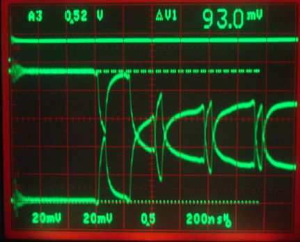
The command transmission begins with a 50-ns low pulse. This pulse appears on both T+ and T−, but the two do not cross over, and we detect no start bit. The separation of the T+ and T− signals during a long HI period is 900 mV. For traces of T+ at the device and T+ at the controller, see here. If we switch to 10-kΩ pull-up and pull-down resistors, we see the following.
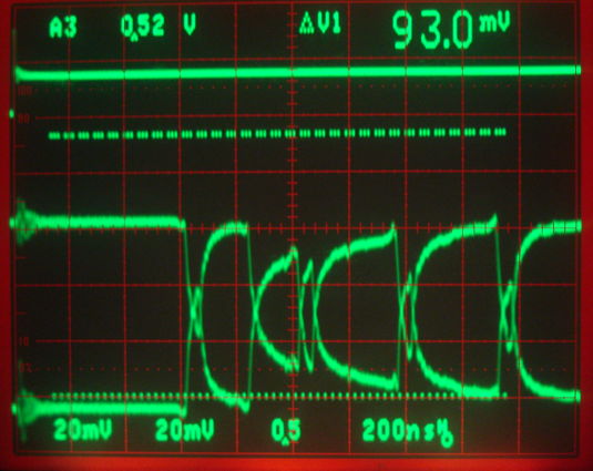
The separation of T+ and T− during a long HI is now 600 mV. The two signals cross during the 50-ns pulse. For traces of T+ at the device and T+ at the controller, see here. In both cases, we see the distortion of the original T+/T- signals by the 120-m cable. The command transmission is made up of high frequencies, represented by the sharp 400-mV transitions, and low frequencies, represented by the shift in the logic HI level of T+ over a few microseconds. Low frequencies travel slower than high frequencies, and so arrive later. But high frequencies are attenuated by their journey down the cable. These two effects combine to produce a failure of the 50-ns pulse when we T+ and T− are pulled apart by 900 mV with 1-kΩ resistors. With 10 kΩ resistors, the 600 mV permits reception of the command. But we see the same failure taking place with a 160-m cable.
[22-MAY-19] When we built our first LWDAQ drivers and devices, we discovered that SN65LVDS180D did not enter its high-impedance state when its driver was disabled. We reported this problem to Texas Instruments, they reproduced the problem, and confirmed our observation. The SN65LVDM180D, however, entered its high-impedance state correctly. We recommended against the use of the SN65LVDS180D from 2002-2018. We now look for this same problem with newly-purchased SN65LVDS180D devices. We take an N-BCAM Head A2083 and connect it to a LWDAQ controller through an RJ-45 Union (A2039). We cut the R+/R− lines on the union, so they do not return to the controller. Instead we pull both lines up to +5V with 100 Ω resistors. We start with an SN65LVDM180D on the A2083 and send consecutive wake and loop-back commands to the device to enable and disable the R+/R− driver.
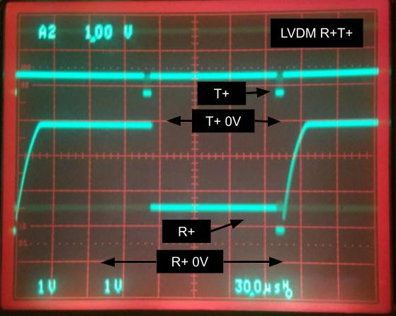
We replace the SN65LVDM180D with an SN65LVDS180D. The SN65LVDS180D device's high-impedance state now works correctly. We assume the manufacturer fixed the problem at some point in the intervening years. We still recommend the SN65LVDM180D, however, because of its lower current consumption and higher drive current.